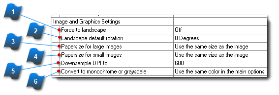
Image and Graphic Settings
Scanned images and electronically created graphic files usually contain size and orientation information. However, when converting to either PDF or DWF, it is necessary to have additional controls to achieve reliable output. For example, most engineering scans that are 36" x 48" in size are portrait in orientation. This is because engineering size scanners have a 36" throat preventing the drawings from being scanned with a landscape orientation. Thus, rotating the scans to proper orientation will keep the PDF and DWF files consistent for viewing and printing.
Hint: Users can preview a PLT in the viewer and select the rotate view button

several times to achieve proper orientation on a file by file basis. The final rotation value is maintained for the current conversion and can be stored and retrieved by saving to a AcroPlot Pro "Plot List File" (PPF)
[File > Save Plot List As...] .
 Force to LandscapeWhen ''On'', all graphic image files that have a larger value in the Y direction than X will be rotated 90 degrees counterclockwise to ensure proper viewing and print orientation.
|
|
 Landscape Default RotationSpecifies the angle (Clockwise) to rotate image files when "Force to Landscape" option is enabled.
|
|
 Papersize for Large ImagesSpecifies the paper size and scale to use for images that are over 8.5'' x 11'' for conversion output.
-
Use Same Size as the Image - This setting will create the paper size to match the image size.
-
Force to Standard Size at 1:1 Scale - This setting will determine the conversion output paper size from the image size and center the file on a standard sheet size at 1:1 scale. This setting will not change the scale of the source file.
-
Force to Standard Size and Scale-to-Fit - This setting will determine the conversion output paper size from the image and center the file on a standard sheet size with a Scale-to-Fit applied. This setting will scale-to-fit the image file to the standard sheet size that is automatically determined by its outer image regions.
-
Use Sheet Size and Plot Scale from the AutoCAD Layout Settings - This setting will use the paper size and plot scale specified in the ''AutoCAD Layout Settings'' within the ''AutoCAD Options'' tab.
|
|
 Papersize for Small Images-
Force to Standard Size at 1:1 Scale - This setting will determine the conversion output paper size from the image size and center the file on a standard sheet size at 1:1 scale. This setting will not change the scale of the source file. -
Force to Standard Size and Scale-to-Fit - This setting will determine the conversion output paper size from the image and center the file on a standard sheet size with a Scale-to-Fit applied. This setting will scale-to-fit the image file to the standard sheet size that is automatically determined by its outer image regions. -
Use Same Size as the Image
|
|
 Downsample DPIDownsample the image DPI settings to a lower setting which will typically create smaller file sizes.
|
|
 Convert to Monochrome or GrayscaleSpecifies settings for how image files will be converted.
-
Use Same Color from the General Options - This setting will use the ''Plot Color'' setting for the conversion output that is specified in the ''General Options'' on the ''Options'' tab. -
Color - This setting will convert image files as presented with no change or modification of color. -
Monochrome - This setting will convert image files to monochrome black and white. -
Grayscale - This setting will convert image files to 256 grayscale.
|
|