Lines Merge Output
Lines merge is a print control for rendering entities in a CAD or PLT file to be transparent wherever they overlap. While many printer and plotter drivers support this function for physical printing to paper, the same doesn't hold true for many software applications that convert to digital PDF files.
AcroPlot Pro supports the lines merge control for digital conversion to a PDF and DWF. Below are two examples that illustrate output to a digital file with and without the lines merge function. Click on the following link download a copy of the AutoCAD file used to create these screen caputres. AcroPlot-256-Sample.dwg
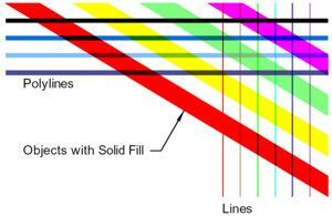
Lines Merge Enabled
The screen capture below is from a PDF that was created using AcroPlot Pro to convert an AutoCAD DWG file with the lines merge function enabled. It shows how the overlapping entities in AutoCAD are treated when creating a PDF or DWF file. Upon close inspection, the polylines that intersect the diagonal objects with a solid hatch fill are transparent where they overlap. In the upper right area of the screen capture, there are instances where lines, polylines, and objects with a solid hatch fill all overlap at the same time. This PDF will view and print exactly as it would from AutoCAD.

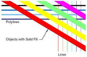
Lines Merge - OFF
The screen capture below is from a PDF that was created using AcroPlot Pro to convert an AutoCAD DWG file with the lines merge function turned off. CAD entities are rendered to the PDF file in the order they are drawn or created. The actual draw order can be determined by looking on the upper right corner--lines first, then polylines, and finally objects with a solid hatch fill. This PDF file will print the same as it is displayed, which is NOT the same as it would from AutoCAD.


